When a pressure gauge displays abnormal readings—whether critically low or dangerously high—immediate action becomes essential to prevent equipment failure, safety incidents, or system downtime. Understanding how to interpret these readings and respond appropriately can mean the difference between routine maintenance and catastrophic failure. This comprehensive guide walks you through the diagnostic steps, corrective measures, and preventive strategies needed when your pressure gauge indicates values outside normal operating parameters, ensuring both equipment longevity and workplace safety.
Pressure gauges serve as critical monitoring instruments across industrial applications, from fire suppression systems to hydraulic equipment and process control environments. When these instruments signal pressure deviations, they're providing early warnings of potential problems that require systematic investigation. The challenge lies not just in recognizing abnormal readings but in understanding their root causes and implementing appropriate corrective actions. Whether dealing with a gradual pressure decline or a sudden spike beyond safe limits, following a structured troubleshooting methodology helps restore system integrity while protecting personnel and assets from pressure-related hazards.
Understanding Normal Pressure Parameters and Deviation Indicators
Establishing Baseline Operating Ranges for Your System
Every pressure system operates within manufacturer-specified parameters that define safe and efficient performance boundaries. For fire extinguisher systems, acceptable pressure typically ranges between 195 and 250 psi at room temperature, though specific thresholds vary by extinguisher type and agent. Industrial hydraulic systems may operate anywhere from 500 to 5000 psi depending on application requirements. Before responding to any pressure gauge reading, you must first understand what constitutes normal for your specific equipment. This baseline knowledge comes from reviewing technical documentation, installation manuals, and maintenance records that document historical operating pressures under various load conditions.
Establishing these baselines requires consideration of environmental factors that legitimately affect pressure gauge readings. Temperature fluctuations cause predictable pressure variations—roughly 5 psi per 10 degrees Fahrenheit in sealed systems containing compressed gases. Altitude differences similarly impact readings in barometric pressure-sensitive applications. Documenting these variables creates context for distinguishing between normal operational drift and genuine system faults requiring intervention. Many facilities maintain pressure log books where operators record daily readings, creating trend data that reveals gradual degradation before critical thresholds are breached.
Recognizing Critical Threshold Violations
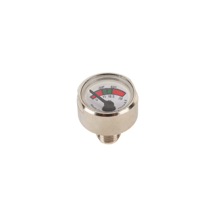
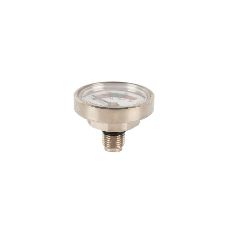
Critical pressure thresholds represent boundaries beyond which continued operation poses safety risks or equipment damage becomes likely. High-pressure violations typically occur when readings exceed 110 percent of maximum allowable working pressure, triggering immediate shutdown protocols in properly designed systems. Low-pressure conditions become critical when readings fall below minimum functional thresholds—for example, when a Pressure Gauge on a fire suppression system drops into the red zone, indicating insufficient agent pressure to guarantee effective discharge during emergencies. These critical thresholds aren't arbitrary but are calculated based on material stress limits, seal integrity boundaries, and functional performance requirements.
Visual indicators on analog pressure gauge faces typically employ color-coded zones—green for normal operation, yellow for caution ranges, and red for critical deviations. Digital pressure gauges may feature programmable alarms that activate when preset limits are exceeded. Understanding these indicator systems enables rapid assessment during routine inspections. However, relying solely on visual indicators without understanding underlying pressure values can lead to misinterpretation, particularly when gauges are improperly calibrated or when colored zones don't accurately reflect your specific system's requirements. Always cross-reference visual indicators against documented specifications to ensure appropriate response protocols are triggered.
Distinguishing Between Gauge Malfunction and Actual Pressure Issues
Not every abnormal pressure gauge reading reflects genuine system pressure problems—sometimes the issue lies within the gauge itself. Mechanical pressure gauge failures manifest through needle drift, sticking pointers, dial face condensation, or physical damage to the Bourdon tube mechanism. Electronic pressure gauge malfunctions may present as erratic digital displays, communication errors, or readings that don't correlate with system behavior. Before initiating extensive system diagnostics or shutdowns, performing quick gauge validation checks can save considerable time and resources while preventing unnecessary production interruptions.
Simple validation techniques include tapping the gauge face gently to see if the needle repositions, comparing readings against a calibrated reference gauge temporarily installed in parallel, or checking for obvious physical damage like cracked lenses or corroded connections. For systems equipped with redundant pressure monitoring, comparing multiple gauge readings provides immediate confirmation of accuracy. When doubt exists about gauge reliability, replacement with a known-accurate instrument should precede major system interventions. This diagnostic sequence—verifying instrument accuracy before assuming system fault—represents fundamental troubleshooting discipline that prevents misguided corrective actions based on false data.
Systematic Response Procedures for Low Pressure Conditions
Immediate Safety Assessment and System Isolation
When a pressure gauge indicates unexpectedly low readings, the first response involves assessing immediate safety implications and determining whether continued operation poses risks. In fire protection systems, low pressure compromises emergency response capability and may violate code compliance, requiring immediate notification to facility safety personnel and possibly temporary compensatory measures like fire watches. In process systems, low pressure might indicate loss of containment, potentially releasing hazardous materials or allowing contaminants into sealed environments. The severity of low-pressure conditions dictates whether immediate shutdown is necessary or whether operation can continue under monitoring while investigation proceeds.
System isolation procedures vary by application but generally involve controlled shutdown sequences that prevent secondary damage. For pressurized vessels, this might mean closing supply valves while venting residual pressure through controlled release points. For hydraulic systems, isolation includes stopping pump operation and securing flow control valves to prevent fluid loss. Throughout isolation procedures, continuous monitoring of the pressure gauge provides feedback on whether the low-pressure condition is static, continuing to decline, or stabilizing. This real-time data informs subsequent diagnostic steps and helps prioritize response urgency based on rate of pressure loss.
Identifying and Addressing Common Leak Points
Pressure loss in sealed systems almost always indicates leakage, making leak detection the primary diagnostic focus when pressure gauge readings drop below normal ranges. Systematic leak checking begins at the most common failure points—threaded connections, valve stems, seal faces, and flex hose assemblies. Visual inspection may reveal obvious leaks through staining, frost formation in refrigerant systems, or audible hissing in pneumatic applications. For less obvious leaks, ultrasonic leak detectors, soap solution applications, or specialized tracer gas methods help locate minute pressure losses that gradually deplete system pressure over time.
Once identified, leak remediation depends on location and severity. Minor weeping at threaded connections often responds to careful re-torquing to specification using calibrated wrenches. Valve stem leaks may require packing adjustment or replacement. More significant leaks at welded joints, corroded pipe sections, or failed pressure vessels demand component replacement rather than temporary repairs. Throughout repair procedures, the pressure gauge serves as validation tool—after corrections, the system should hold pressure within specifications during leak testing periods. Failure to maintain pressure after apparent leak repairs suggests either incomplete repair or additional leak points requiring further investigation.
Evaluating and Correcting Charge Loss in Sealed Systems
In permanently sealed systems like fire extinguishers or closed-loop refrigeration equipment, pressure gauge readings reflect the charge quantity of contained gases or vapors. Low pressure in these applications indicates charge loss through either leakage or chemical decomposition. For CO2 fire extinguishers, pressure gauge readings directly correlate with agent weight—a gauge reading in the recharge zone indicates the cylinder has lost sufficient agent to compromise fire suppression effectiveness. These systems require professional recharging services that evacuate residual contents, leak-test the container, and refill to manufacturer specifications using properly certified agents.
Charge loss evaluation begins with weighing the container if specifications provide target weights, offering definitive confirmation of contents regardless of pressure gauge accuracy. For systems where weighing isn't practical, pressure-temperature charts help determine whether observed pressure gauge readings align with expected values for the charge quantity and ambient conditions. Significant deviations between calculated and actual readings suggest either gauge error or charge contamination affecting pressure behavior. Correcting charge loss extends beyond simply adding more agent—proper procedures include identifying why loss occurred, repairing the failure point, and following manufacturer protocols for evacuation, leak testing, and recharging to ensure reliable future performance.
Systematic Response Procedures for High Pressure Conditions
Emergency Pressure Relief and System Protection
High-pressure conditions pose immediate burst risks, making rapid pressure reduction the priority response when pressure gauge readings enter danger zones. Most properly designed pressure systems incorporate automatic relief devices—safety valves, rupture discs, or pressure relief valves—calibrated to open before catastrophic failure occurs. When high pressure is observed on a pressure gauge, immediately verify that relief devices are functional and not blocked, corroded, or improperly set. If manual intervention is required to reduce pressure, controlled venting through designated relief ports prevents uncontrolled release while bringing the system back within safe operating limits.
Emergency pressure reduction procedures must account for the nature of contained fluids or gases. Venting toxic, flammable, or corrosive substances requires appropriate containment and environmental controls to protect personnel and comply with regulations. For hydraulic systems showing high pressure on pressure gauges, reducing pump output or opening bypass valves provides controlled pressure reduction without complete system shutdown. Throughout pressure reduction, continuous monitoring ensures pressure decreases at controlled rates that prevent thermal shock, cavitation, or other phenomena that might cause secondary damage. Once pressure stabilizes within safe ranges, investigation of root causes can proceed without immediate rupture risks.
Diagnosing Causes of Pressure Buildup
Abnormally high pressure gauge readings typically result from either excessive input, restricted output, or thermal expansion in sealed systems. In pumped systems, excessive input occurs when pump capacity exceeds demand, control valves malfunction, or variable speed drives operate at inappropriate speeds. Diagnostic procedures include verifying pump output against design specifications, checking control system setpoints, and confirming that demand-side equipment is operating normally. Pressure gauge trends over time help distinguish between sudden pressure spikes suggesting acute failures and gradual pressure increases indicating developing restrictions or control drift.
Restricted output conditions develop when blockages, closed valves, or clogged filters prevent normal flow, causing pressure to build behind the obstruction. Systematic checking of flow paths from source to destination identifies restriction points. For filter-equipped systems, checking differential pressure across filters quickly reveals whether excessive dirt loading is restricting flow and driving up upstream pressure visible on system pressure gauges. In thermal systems, heat input without adequate expansion accommodation causes pressure buildup—common in sealed hot water systems, compressed gas cylinders exposed to heat sources, or refrigeration systems with restricted condenser airflow. Each cause requires specific corrective action matched to the root mechanism driving pressure elevation.
Correcting Control System Failures and Setpoint Issues
Modern pressure systems rely on automated controls that maintain pressure within target ranges by modulating pumps, compressors, valves, or other actuators based on pressure gauge feedback. When these controls fail, pressure regulation fails, often resulting in high-pressure conditions. Pressure switch failures, controller programming errors, sensor malfunctions, or actuator problems all disrupt normal regulation. Diagnosing control system issues requires methodical testing of each component—verifying that pressure sensors provide accurate signals to controllers, confirming controllers generate appropriate command outputs, and ensuring final control elements respond correctly to commands.
Setpoint configuration errors represent another common source of high-pressure conditions, particularly after maintenance activities, control system updates, or operational changes. If someone incorrectly programs pressure control setpoints higher than safe system limits, the control system will dutifully maintain these dangerous pressures until the error is corrected. Reviewing control system configuration against design documentation and physical system nameplates helps identify setpoint discrepancies. Many facilities implement change control procedures requiring engineering review before pressure setpoint modifications specifically to prevent such errors. When control system issues are identified, corrections may range from simple sensor recalibration to complete controller replacement, depending on failure mode and component condition.
Preventive Maintenance Strategies to Avoid Pressure Deviations
Establishing Regular Pressure Gauge Calibration Programs
Accurate pressure measurement depends on maintaining pressure gauge calibration throughout service life. Industrial pressure gauges typically require calibration verification annually, with more frequent intervals for critical safety applications or harsh operating environments. Calibration programs compare gauge readings against traceable pressure standards across the operating range, documenting accuracy and adjusting or replacing gauges that exceed allowable error tolerances. These programs prevent situations where operators respond to inaccurate gauge readings, potentially overlooking genuine pressure problems or taking unnecessary corrective actions based on false indications.
Implementing effective calibration programs involves maintaining calibration records for each pressure gauge, scheduling calibrations based on manufacturer recommendations and regulatory requirements, and using qualified calibration laboratories or certified in-house standards. For facilities with numerous pressure gauges, color-coded calibration tags displaying next-due dates enable quick visual verification of calibration status during inspections. Digital pressure gauges with built-in diagnostics may signal when performance drift suggests calibration needs, enabling condition-based rather than purely time-based calibration scheduling. Regardless of approach, systematic calibration prevents the accuracy degradation that otherwise compromises pressure monitoring reliability.
Implementing Systematic Inspection and Testing Protocols
Routine inspection catches developing pressure problems before they escalate to critical failures visible on pressure gauges as extreme deviations. Inspection protocols should include visual examination of gauge condition, checking for physical damage, verifying readability, and confirming proper mounting. Beyond the gauge itself, inspections examine associated system components—pressure relief devices, isolation valves, piping connections, and pressurized vessels—looking for corrosion, mechanical damage, or other degradation that might eventually cause pressure loss or dangerous buildup.
Testing protocols complement visual inspections with functional verification. Pressure relief valve testing confirms these critical safety devices will activate at proper setpoints, preventing over-pressure conditions that would otherwise register on pressure gauges as dangerous readings. Leak testing of sealed systems verifies containment integrity before significant charge loss occurs. Hydrostatic or pneumatic pressure testing of vessels and piping systems confirms structural integrity to contain design pressures safely. These proactive testing activities, scheduled based on risk assessment and regulatory requirements, identify potential failures during controlled maintenance windows rather than during emergencies when pressure gauge readings signal problems during critical operations.
Training Personnel on Proper Response and Reporting
Even the most sophisticated pressure monitoring systems prove ineffective if personnel don't understand how to interpret pressure gauge readings and respond appropriately. Comprehensive training programs ensure operators recognize normal versus abnormal readings, understand when immediate action is required versus when engineering consultation is appropriate, and follow established protocols for pressure-related incidents. Training should cover the specific pressure systems each person works with, including normal operating ranges, common failure modes, and step-by-step response procedures for both high and low pressure conditions indicated by pressure gauge readings.
Effective training extends beyond initial orientation to include periodic refreshers, updates when systems change, and practical exercises using simulators or training systems where personnel can practice responses without risking actual production equipment. Establishing clear reporting requirements ensures that abnormal pressure gauge observations are documented and communicated to maintenance personnel who can investigate root causes and implement corrections. Many facilities use standardized reporting forms that capture essential details—gauge identification, observed reading, date and time, environmental conditions, and any actions taken—creating documentation that supports trend analysis and continuous improvement of pressure management practices.
FAQ
How quickly should I respond when my pressure gauge shows a reading in the red zone?
Immediate response is required when pressure gauge readings enter red zones indicating critical conditions. For high-pressure situations, initiate emergency pressure relief procedures within minutes to prevent potential rupture or explosion hazards. For low-pressure conditions, assess whether the system provides critical safety functions—if so, implement compensatory measures immediately while investigating the cause. In all cases, red-zone readings warrant stopping normal operations until the situation is evaluated by qualified personnel and either corrected or determined to be a gauge malfunction rather than actual system pressure problem.
Can I continue operating equipment if the pressure gauge shows slightly low readings but still in the yellow caution zone?
Continued operation with pressure gauge readings in caution zones depends on several factors including the rate of pressure change, the criticality of the equipment function, and whether operation in this range violates regulatory requirements or manufacturer specifications. Generally, caution-zone readings warrant increased monitoring frequency and expedited investigation while operation may continue temporarily if safety is not compromised. However, for fire protection systems, even yellow-zone readings typically require service within specified timeframes due to code compliance requirements. Always consult equipment documentation and facility procedures that define acceptable operating ranges and required responses for your specific application.
What's the difference between a gauge reading incorrectly versus actual system pressure being abnormal?
Distinguishing between pressure gauge malfunction and genuine pressure problems requires verification techniques. Gauge malfunction often presents as sudden reading changes without corresponding system behavior changes, needle sticking or vibration, or readings that don't respond to known pressure changes. Actual pressure problems typically show gradual trends, correlate with system performance changes, and appear consistently across multiple monitoring points if redundant gauges exist. Quick verification involves installing a calibrated reference gauge temporarily alongside the suspect gauge—if readings differ significantly, gauge replacement is needed. For critical applications, always assume readings are accurate until proven otherwise to avoid overlooking genuine safety hazards.
How often should I check pressure gauges in different types of systems?
Inspection frequency for pressure gauge monitoring varies by application criticality and regulatory requirements. Fire extinguisher pressure gauges require monthly visual checks per NFPA standards, with annual professional inspection. Industrial process systems typically need daily operator checks of critical pressure points, with weekly inspection of secondary monitoring points. Systems in harsh environments or those with history of pressure instability may warrant continuous monitoring through automated systems with alarm capabilities. Establish inspection frequencies based on failure consequence analysis—systems where pressure deviations pose immediate safety risks or significant economic impact warrant more frequent monitoring than non-critical applications. Always follow manufacturer recommendations and applicable codes as minimum requirements, increasing frequency based on operating experience and risk assessment.
Table of Contents
- Understanding Normal Pressure Parameters and Deviation Indicators
- Systematic Response Procedures for Low Pressure Conditions
- Systematic Response Procedures for High Pressure Conditions
- Preventive Maintenance Strategies to Avoid Pressure Deviations
-
FAQ
- How quickly should I respond when my pressure gauge shows a reading in the red zone?
- Can I continue operating equipment if the pressure gauge shows slightly low readings but still in the yellow caution zone?
- What's the difference between a gauge reading incorrectly versus actual system pressure being abnormal?
- How often should I check pressure gauges in different types of systems?

